


Wave Summation
This page is a basic overview of the maths involved in adding sinusoidal signals. This forms a central part of analysing a beamformer's spacial response.
Wave Propagation and Summation
The image below depicts a typical, although simplified, microphone array beamforming setup. A wavefront travelling from the speaker will reach the microphones at different times, this property is the very essence of an array's spatial filtering ability. When simulating an array's spatial filtering performance, it is necessary to calculate how the microphone signals sum together for different signal source positions or angles.
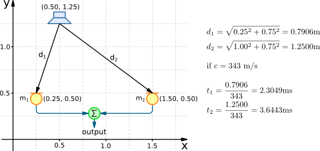
Based on the speaker and microphone positions it is possible to first calculate the distance a wavefront travels, then for a given speed of sound, the time it takes for the wavefront to leave the speaker and reach each microphone. For a more thorough description of calculating these delay times in both 2D and 3D, take a look at the Delay Calculation page.
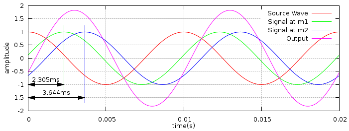
The plot below shows a 100Hz 'Source Wave' representing a signal leaving the speaker. The plot also shows the 'Signal at microphone 1' and the 'Signal at microphone 2'. The delays caused by propagation of the source signal to the microphones is clearly seen. Finally the array's 'Output' (the sum of the two microphone signals) is shown. Rather than having an amplitude of twice the source wave (there being two microphones), the output has an amplitude of 1.825, due to the difference in propagation time.
Note: The attenuation of the signal as it travels from the speaker to the microphones has not been considered.
Using Phasors to Calculate Amplitude
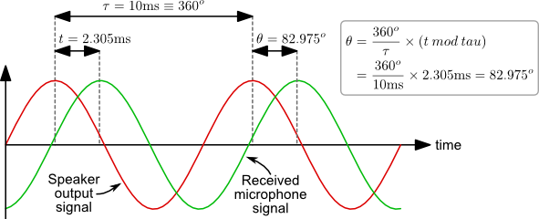
A simple approach to calculating the amplitude of the combined microphone signals (the array's output) is to use phasors. The figure below shows how the phase difference between two signals is calculated. One period of a wave corresponds to 360°, given a period of 10ms, a delay of 2.305ms corresponds to a phase shift of 82.975°.
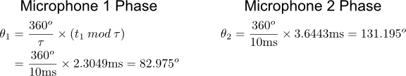
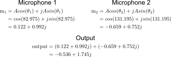
The phase calculation for both microphone signals is shown below.
A phasor plot provides a method for representing a sine wave's amplitude and phase. They also provide a graphical method of adding waves. The three phasor diagrams represent the two microphone signals and the array's output. The phasor length corresponds to the wave's amplitude, the angle corresponds to the phase. These are plotted as vectors on a complex axis. The phasor summation is achieved very easily by adding the vectors, the resulting vector represents the summed wave.
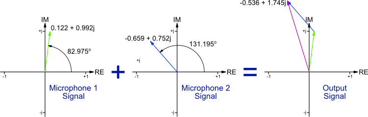
The simplest method to summing the vectors is to convert them from their polar coordinates (amplitude and phase) to their Cartesian coordinates (real and imaginary). Then the output vector is easily calculated from the sum of the two microphone vectors.
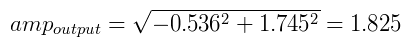
The final step to calculating the amplitude of the summed wave is to calculate the length of the summed vector using Pythagoras' theorem, as shown below.
Simplified Form
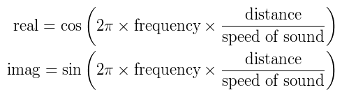
By combining the above stages the following formula can be derived for calculating a wave's complex representation based on its frequency, distance travelled and the speed of sound. To sum a collection of waves, just calculate and sum the real and imaginary parts for each wave, then use Pythagoras' theorem to calculate the final amplitude.
The following piece of c code performs the wave summation calculations for the two microphone setup described above.
waves.c#include <stdio.h> #include <math.h> int main(void) { double phase, distance, delay; double freq = 100.0; // Hz double speedSound = 343.0; // m/s // Microphone 1 distance = sqrt(0.25*0.25 + 0.75*0.75); delay = distance / speedSound; double re1 = cos(2.0 * M_PI * freq * delay); double im1 = sin(2.0 * M_PI * freq * delay); phase = 180 * atan2(im1, re1) / M_PI; printf("Mic1 - Distance:%.4f, Delay:%.4f, Phase:%.3f, [%.3f %.3f]\n", distance, delay*1000, phase, re1, im1); // Microphone 2 distance = sqrt(1.00*1.00 + 0.75*0.75); delay = distance / speedSound; double re2 = cos(2.0 * M_PI * freq * delay); double im2 = sin(2.0 * M_PI * freq * delay); phase = 180 * atan2(im2, re2) / M_PI; printf("Mic2 - Distance:%.4f, Delay:%.4f, Phase:%.3f, [%.3f %.3f]\n", distance, delay*1000, phase, re2, im2); // Output double re = re1 + re2; double im = im1 + im2; double amp = sqrt(re*re + im*im); phase = 180 * atan2(im, re) / M_PI; printf("Output - Amplitude:%.3f, Phase:%.3f, [%.3f %.3f]\n", amp, phase, re, im); return 0; }
The code can be compiled and executed using the commands below.
> gcc -Wall -lm -o waves waves.c
> ./waves
The output shows the polar and Cartesian forms of the microphone and output signals.
Mic1 - Distance:0.7906, Delay:2.3049, Phase:82.975, [0.122 0.992]
Mic2 - Distance:1.2500, Delay:3.6443, Phase:131.195, [-0.659 0.752]
Output - Amplitude:1.826, Phase:107.085, [-0.536 1.745]
Euler's Formula Representation
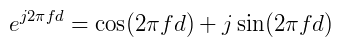
The complex representation of a wave can be presented in a more compact form using Euler's formula. The equations below show Euler's Formula and how it is adapted to represent a wave of frequency f.

For a wave that has a delay of d, the equation takes the form shown below. It can be seem how this matches the equations used in the phasor analysis section above.
Linear Array Example
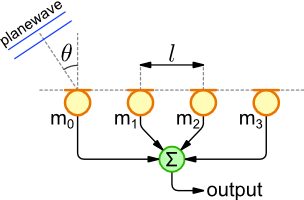
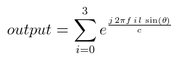
The exponential form is popular in beamforming literature. Below is a simple example of a linear array. Each array element is separated by distance of l metres. For a plane wave of frequency f arriving from an angle θ at a speed of sound c, the arrays output is calculated using the following equation.
|
|
The output amplitude for a linear array is calculated using the phasor and exponential approach below.
array1.c#include <stdio.h> #include <math.h> int main(void) { int numElements = 4; // Number of array elements double spacing = 0.75; // Element separation in metre double angle = 30.0; // Degrees from broadside double freq = 100.0; // Signal frequency in Hz double speedSound = 343.0; // m/s int i; double realSum = 0; double imagSum = 0; // Iterate through array elements for (i=0 ; i<numElements ; i++) { // Calculate element position and wavefront delay double position = i * spacing; double delay = position * sin(M_PI * angle / 180) / speedSound; printf("%3d) Position: %f, Delay: %e\n", i, position, delay); // Add Wave realSum += cos(2.0 * M_PI * freq * delay); imagSum += sin(2.0 * M_PI * freq * delay); } double output = sqrt(realSum * realSum + imagSum * imagSum); printf("Output Amplitude: %.3f [%f, %f]\n", output, realSum, imagSum); return 0; }
array2.c#include <stdio.h> #include <math.h> #include <gsl/gsl_complex.h> #include <gsl/gsl_complex_math.h> int main(void) { int numElements = 4; // Number of array elements double spacing = 0.75; // Element separation in metre double angle = 30.0; // Degrees from broadside double freq = 100.0; // Signal frequency in Hz double speedSound = 343.0; // m/s int i; gsl_complex total; GSL_SET_COMPLEX(&total, 0 ,0); gsl_complex comp; // Iterate through array elements for (i=0 ; i<numElements ; i++) { // Calculate element position and wavefront delay double position = i * spacing; double delay = position * sin(M_PI * angle / 180) / speedSound; printf("%3d) Position: %f, Delay: %e\n", i, position, delay); // Calculate exponential form comp.dat[0] = 0; // Real comp.dat[1] = 2.0 * M_PI * freq * delay; // Imaginary gsl_complex w = gsl_complex_exp(comp); // Exponential // Add Wave total = gsl_complex_add(total, w); // Accumulate } double output = gsl_complex_abs(total); printf("Output Amplitude: %.3f [%f, %f]\n", output, total.dat[0], total.dat[1]); return 0; }
The code can be compiled and executed using the commands below.
> gcc -Wall -lm -o array1 array1.c
> ./array1
> gcc -Wall -lm -lgsl -o array2 array2.c
> ./array2
The output for both programmes is identical as they are both calculating the same thing, although in slightly different ways. The output shows the physical position of each array element in metres and the wavefront delay with regards to the first microphone. The amplitude of the summed signals is also show with it's complex representation.
0) Position: 0.000000, Delay: 0.000000e+00
1) Position: 0.750000, Delay: 1.093294e-03
2) Position: 1.500000, Delay: 2.186589e-03
3) Position: 2.250000, Delay: 3.279883e-03
Output Amplitude: 2.912 [1.498204, 2.497171]
Page Revisions
| Rev Number | Date | Details |
|---|---|---|
| 1.1 | 9/3/2011 | Corrected equation in Linear Array Example section. |
