


Composite Arrays
The standard equally spaced linear array (as described on the Delay Sum page) has a beam pattern that is dependant on frequency, As the frequency reduces, the width of the main lobe increases. This is a problem when trying to spatially filter a broadband signal; ideally a constant main-lobe width is desirable for the whole frequency range of interest.
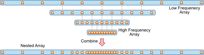
A simple solution to this problem is the composite, or nested, array. This is simply a combination standard arrays each configured to provide spatial filter for a sub-band of the required frequency range. Such as array is shown below.
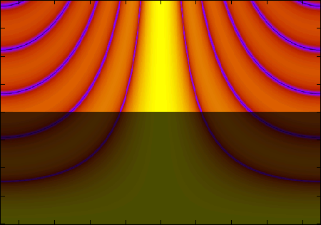
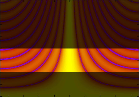
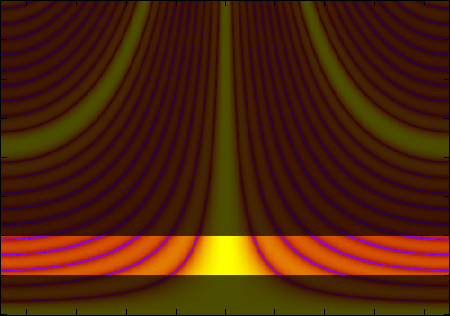
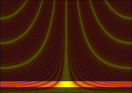
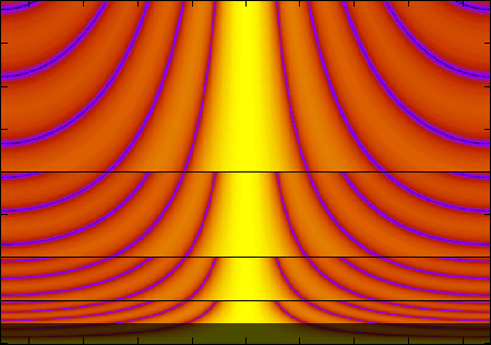
The beam patterns for each of these arrays are shown in the plots below. Frequency on the vertical axis (0 to 8kHz), angle on the horizontal axis (-90 to 90 degrees). The shaded areas are filtered out using a band-pass filter.
Sub Array, 11 elements, 0.02m spacing |
Sub Array, 11 elements, 0.04m spacing |
Sub Array, 11 elements, 0.08m spacing |
Sub Array, 11 elements, 0.16m spacing |
When the output from each array is summed, the beam pattern shown below is produced. The main lobe width is considerable more constant that for a single array.
All Sub Arrays, 29 elements
