


Frost's Algorithm
Frost's algorithm is a long standing (1970's) beamforming technique that reduces noise whilst maintaining the look direction signal. It is an adaptive system that aims to minimal noise energy by adjusting the beamformer filter weights. Although the work was published a while ago, a great deal of current work builds upon and references this work, so it's well worth looking at.
The original publication is cited below. This is well worth getting hold of and reading. It is very well written and generally easy to follow.
An Algorithm For Linearly Constrained Adaptive Array Processing
, Proceedings of the IEEE, Vol 60, Issue 8, Pages 926-935, August 1972 [Link]
The Theory
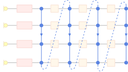
Frost's Algorithm operates on the beamformer structure shown below. Each of the M microphones is connected to a delay stage, then on to a FIR filter. The beamformer output is simply the sum of the FIR filter outputs.
The delay stages are used for steering, such that signals received from the look direction are aligned. This step is exactly that same as that used by the basic Delay-Sum beamformer.
The clever part is the adjustment of the FIR filter tap weights.

The filter-sum beamformer structure used for implementing Frost's Algorithm
Variable Definitions
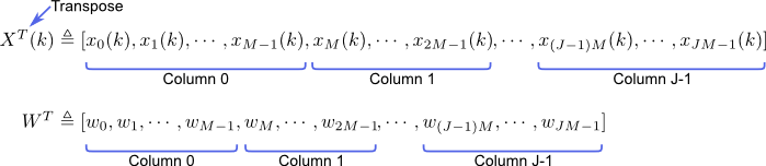
Variable Ordering in vectors
Two vectors are defined below, one for the sampled incoming data, the other for the FIR filter weight values. As illustrated in the diagram to the right, the vectors and made from combining the columns of appropriate values. Therefore, each vector contains M*J elements, where M is the number of microphones and J is the number of taps per FIR filter.
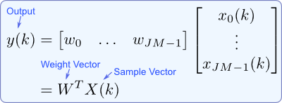
The beamformer output is simply the multiplication of the weight and sample vectors. A quick look at the beamformer diagram shows how this works; the output is simply the total summation of each sampled value along the delay lines multiplied by their connected weight.
Expected Output Power
The expected output power of the array is given by the equation below. 'Expected' basically means the mean average.

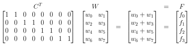
Constraints
To remove the noise from the signal we ideally want to minimise the power of the output's noise component. Therefore we need to constrain the minimisation of the output power such that only the noise power is minimised and the signal of interest remains.
Implementation
