


PC Parallel Port
Information on the PC Parallel port
Parallel Port Hardware
The diagram below shows the pins of the parallel port connector, when looking at the computer's connector.
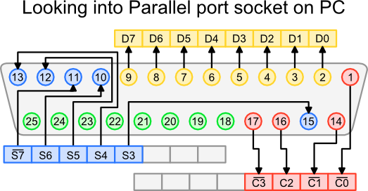
Parallel Port Diagram
The parallel port uses three registers, their bit assignment is shown in the diagram below.
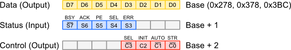
Parallel Port Registers
Descriptions of the different bits are listed in the table below.
|
|
Linux Parallel Port Code
Below are listed two options for controlling the parallel port under Linux.
The first option writes directly to the parallel port memory address. It's
simple and works well, but because of the low level access, you'll need to have
root privileges. The second option, uses the ppdev module for user-space
access, that means you don't need root privileges.
Compile either source file using the following command line.
> gcc cableTest.c -o cableTest
cableTest.c#include <stdio.h> #include <inttypes.h> #include <sys/io.h> #include <signal.h> #define BASE 0x378 int running = 1; void signalHandler(int sig) { running = 0; } int main(void) { printf("Parallel Port Interface Test (Base: 0x%x)\n", BASE); signal(SIGINT, signalHandler); // Set permission bits of 4 ports starting from BASE int result = ioperm(BASE, 4, 1); // If setting permission failed, return if (result != 0) { printf("ERROR: Could not set permissions on ports"); return result; } // This loop will keep running until ctrl-c is pressed while (running) { outb(0xFF, BASE); outb(0x00, BASE); } // Clear permission bits of 4 ports starting from BASE result = ioperm(BASE, 4, 0); if (result != 0) { printf("ERROR: Could not clear permissions on ports"); return result; } return 0; }
User-Mode Access
The code below is the user-mode version. It accesses the parallel port via
the ppdev driver. You'll need to make sure that the driver is compiled into
your kernel, or compiled as a module then loaded. The first command below can
be used to check if the module is loaded, the second will load it.
> lsmod | grep ppdev
> modprobe ppdev
The ppdev kernel driver can be found in the location shown below.
-> Device Drivers
  -> Character Devices
    -> <M> Support for user-space parallel port device drivers
NOTE: Arguments to the ioctl function are passed by pointer, so be careful
when using the functions. This is why mode, dir, dataH and dataL are defined first,
then their addresses are passed to ioctl.
cableTest2.c#include <stdio.h> #include <sys/ioctl.h> #include <linux/parport.h> #include <linux/ppdev.h> #include <fcntl.h> #include <unistd.h> #include <stdlib.h> #include <signal.h> int running = 1; void signalHandler(int sig) { running = 0; } int main(void) { int fd; int result; printf("Parallel Port Interface Test\n"); // Set ctrl-c handler signal(SIGINT, signalHandler); // Open the parallel port for reading and writing fd = open("/dev/parport0", O_RDWR); if (fd == -1) { perror("Could not open parallel port"); return 1; } // Try to claim port if (ioctl(fd, PPCLAIM, NULL)) { perror("Could not claim parallel port"); close(fd); return 1; } // Set the Mode int mode = IEEE1284_MODE_BYTE; if (ioctl(fd, PPSETMODE, &mode)) { perror("Could not set mode"); ioctl(fd, PPRELEASE); close(fd); return 1; } // Set data pins to output int dir = 0x00; if (ioctl(fd, PPDATADIR, &dir)) { perror("Could not set parallel port direction"); ioctl(fd, PPRELEASE); close(fd); return 1; } char dataH = 0xFF; char dataL = 0x00; // This loop will keep running until ctrl-c is pressed while(running) { // Output some data // Note that data is passed by a pointer ioctl(fd, PPWDATA, &dataH); ioctl(fd, PPWDATA, &dataL); } printf("Shutting down\n"); // Release and close the parallel port ioctl(fd, PPRELEASE); close(fd); return 0; }
Signal Termination
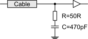
It is important that the data lines from the parallel port are properly terminated. The circuit below shows one of the many forms of cable termination. The resistor value, R, should match the characteristic impedance of the cable. The capacitor value is most easily found with trial and error.
Signal Termination
The figures below show the difference between the unterminated and terminated signal. The component values used are those shown in the figure above.
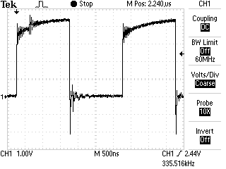
Unterminated Signal |
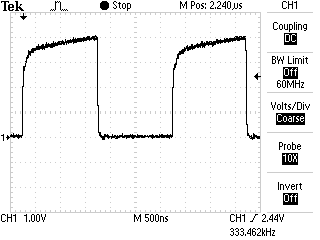
Terminated Signal |
