


MAX3420 - Maxim USB Peripheral Controller
The MAX3420 is a USB peripheral controller chip with an SPI bus. This page hopefully contains enough information to help you easily make use of the device in your projects.
MAX3420 Introduction
The MAX3420 provides a very simple approach to adding a USB interface to a circuit. It uses a SPI bus to connect to your system. It does require a reasonable amount of configuration and control, so you'll need to connect it to some form of microprocessor/microcontroller.
The photos below show a PCB containing a MAX3420 device. The board is designed to connect to a Digilent XUP-V2Pro FPGA development board.
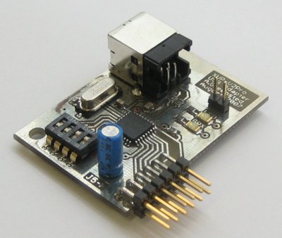
MAX3420 USB Board |
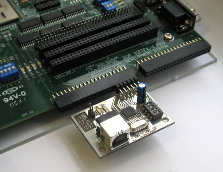
MAX3420 connected to a Digilent XUP-V2Pro |
Circuit & PCB
Below are the Schematic and PCB layouts for the board. Use the link below to download the Eagle CAD files.
The board is driven by a 3.3V supply. The connector pin arrangement allows it to be plugged directly into header J5 of a Digilent XUP-V2Pro FPGA development board, as shown in the right-hand photo above.
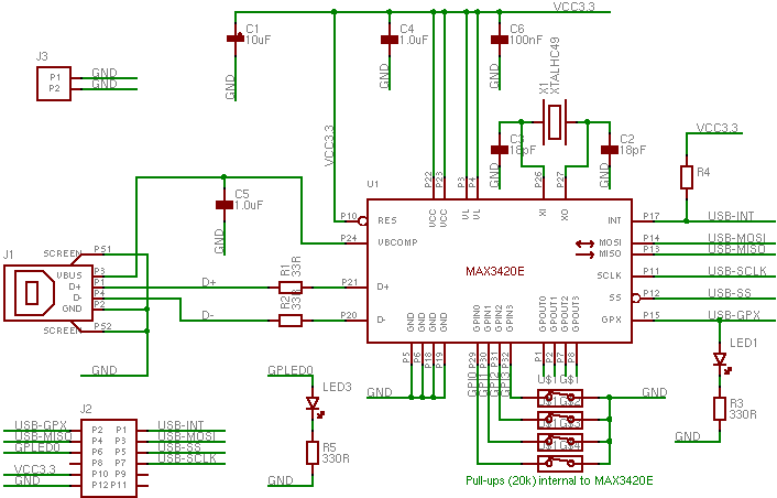
MAX3420 PCB Schematic
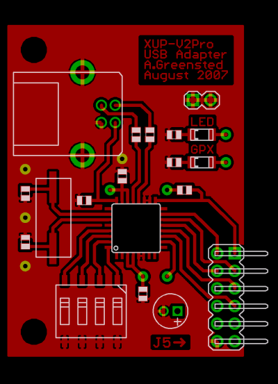
MAX3420 PCB Top Layer
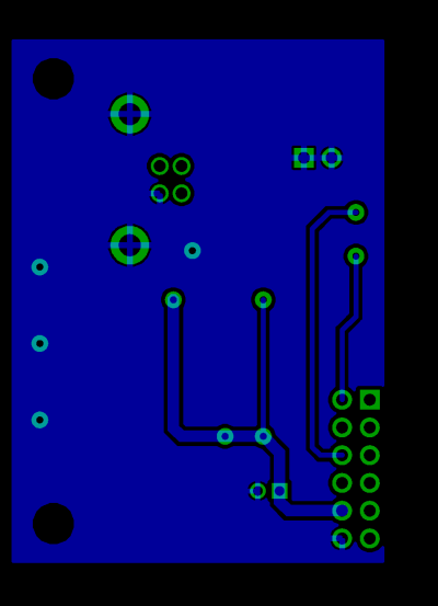
MAX3420 PCB Bottom Layer
Example System
Below is an example setup of using the MAX3420 to connect a PC and a microcontroller embedded on an FPGA. There are 3 main custom parts to this system.
- The MAX3420 PCB. This uses USB to connect to the PC and SPI to connect to the FPGA.
- The Linux device driver. This creates a device file,
/dev/usbDIOthat user applications can read from and write to. - The EDK peripheral that connects the SPI to the OPB bus
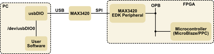
Example MAX3420 Setup
Information on the MAX3420 has already been given above. Details on the Linux device driver and the EDK Peripheral are given below.
Linux Host Driver
You will need a kernel driver in order to send and receive data from the MAX3420 chip. Below is a basic USB driver that will do this. Hopefully all you'll need to do is download the gzipped tar, decompress, and type make.
Loading this module will create the file /dev/usbDIO0. Writing to and reading from this file will
send and receive date from the MAX3420 device.
EDK Peripheral & Driver Code
The EDK peripheral linked to below contains a SPI module that will talk to the MAX3420. Unpack the file and place the max3420_v1_00_a directory into your EDK project's pcores directory.
The table below shows the pad LOC constraints for the XUP-V2Pro J5 Header. You'll need to put these into your system's UCF file.
| Net | LOC |
|---|---|
usb_SCLK | L5 |
usb_SS | M2 |
usb_MOSI | P9 |
usb_MISO | N2 |
usb_GPX | R9 |
usb_INT | M4 |
The module only uses two register locations. The first is used to read the MAX3420 status bits and set the SPI data rate. The second is used to transfer data between the MAX3420 device and the embedded processor. These functions are summarised in the table below.
| Register | Read | Write |
|---|---|---|
| 0 (Base address) | Device Status | SPI speed |
| 1 (Base address + 4) | Data from MAX3420 | Data to MAX3420 |
